Siemens Solid Edge
3D CAD software
Solid Edge is a 3D CAD software that assists you throughout the entire product design process. It has an extensive software portfolio that offers a solution in every area. It also uses synchronous technology, a patented technology that allows you to quickly and easily modify imported files. Siemens also owns the Parasolid kernel used in Solid Edge, which allows it to go further than other 3D CAD software.
MECHANICAL DESIGN
Solid Edge allows you to quickly and efficiently design your ideas in 3D.
With engineering reference intelligence, you can effortlessly design parts such as gears, cams, springs, and bars. The modeling of complex stylized shapes is possible through the Subdivision Modeling feature.
In addition, Solid Edge offers many other features.

METAL CONSTRUCTION
Easily manufacture your sheet metal parts thanks to the numerous features within Solid Edge.
Unfolding becomes a breeze, and you have enough features to unfold exactly according to the parameters of your machine park.
Profiled metal structures can be quickly created in the frame design environment, giving you complete freedom to determine the shape and connections you want. It is also possible to use a machine library to quickly use standard parts.
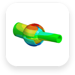
Simulations
Optimize and validate your design digitally with the simulation capabilities of Solid Edge.
Simulate strength calculations, heat transfer, the inflection point, and many other things…
Solid Edge Simulation uses the renowned Femap FEM technology from Simcenter.
RENDERING
Solid Edge also allows you to create realistic renderings using KeyShot.
The seamless connection between Solid Edge and KeyShot enables you to create stunning visuals from your 3D models in just a few steps.
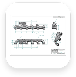
TECHNICAL DRAWINGS
Create 2D drawings in Solid Edge effortlessly using the View Wizard, which automatically places your views.
You can easily add dimensions or annotations. Import DXF or DWG drawings directly into Solid Edge and adapt them to your needs.
Your production drawings have never looked so clear and beautiful!
Solid Edge 2025: Innovative Features for Optimized Product Design
Solid Edge 2025 introduces a secure SaaS version with Solid Edge X, along with new artificial intelligence (AI) tools to work more efficiently. It also includes a series of enhancements aimed at speeding up design processes, featuring improved engraving and bending functions for sheet metal applications, as well as support for Model-Based Definition (MBD).
Expand your toolbox to accelerate innovation with advanced features available on demand through token-based licensing packs, and enjoy seamless integration with solutions from the Siemens Xcelerator portfolio.
SOLID EDGE Modules
SOLID EDGE 2D DRAFTING
Whether you need to use 2D CAD software across your entire company or for a specific 2D design process, Solid Edge 2D Drafting provides a free, production-proven 2D drawing software. With a familiar user interface, easy-to-use tools, and capabilities that comply with the most popular drawing standards, Solid Edge 2D Drafting has everything you need to quickly and easily create 2D documentation, to simplify your experience.
Solid Edge 2D Drafting offers simple layout, diagram, annotation, and drawing dimensioning commands that automatically comply with drawing standards, including those of the International Organization for Standardization (ISO), the American National Standards Institute (ANSI), and the British Standards Institution (BSI), among others. Start your drawing from scratch or easily import existing .DWG files. A step-by-step wizard allows you to preview the drawing, including each individual layer, and control the background color, drawing size, line type, font, etc.
To simplify the learning curve for new and existing 2D CAD users, Solid Edge 2D Drafting offers several ways to access commands, such as a recognizable ribbon toolbar, simple text search, and a customizable radial menu that provides quick access to your favorite tools. When you’re done, you can save your file in Solid Edge or .DWG format, allowing you to collaborate with your clients, peers, and partners, and easily open your 2D CAD files in almost any 3D CAD program.
SOLID EDGE ELECTRICAL
Quickly and easily add cables and wires to your mechanical project.
Connect different terminals to each other using smart tools.
Generate BOM lists of all parts, including both mechanical and electronic parts such as cables, wires, and connectors.
SOLID EDGE HARNESS DESIGN
Solid Edge Harness Design includes intelligent libraries for components and symbols that control the automatic selection of terminals, seals, and wires.
A powerful part selector configures the terminals, seals, and wires for each connector. Connector surface views and tables allow designers to easily determine how wires are connected.
You can design cable harnesses in standalone mode, or they can be derived from the wiring provided by Solid Edge Wiring Design.
Once a harness is completed, the powerful reporting capabilities help generate the necessary documentation for production, including parts lists and cable lengths.
SOLID EDGE CAM PRO
Solid Edge production solutions help manufacturers define and implement a wide range of traditional and new production processes, including CNC machining, nesting, cutting, bending, casting, welding, assembly, and additive manufacturing.
The software solutions work directly on your Solid Edge models of parts, sheet metal, and assemblies, enabling precise and efficient manufacturing processes.
Manufacturing instructions created with these solutions can be easily updated to reflect any changes in the underlying design.
SOLID EDGE PIPING DESIGN
Solid Edge Piping Design offers automated 3D piping design with extensive libraries of 3D parts and fully automated Isogen® output in PDF format for plant design.
Pipes and tubes of the same length but different assemblies—even if bent differently—retain the same BOM number, reducing the introduction of errors during purchasing and production.
The software includes powerful 3D piping drawing features that allow even inexperienced users to easily create 3D sketches.
SOLID EDGE XPRESROUTE
Solid Edge XpresRoute streamlines the design of mechanical routing systems in a 3D environment, creating piping systems according to the most efficient design.
Once the design is complete, Solid Edge XpresRoute continues to increase productivity and reduce costs by automatically generating detailed reports, BOMs, and other valuable purchasing and production information.
SOLID EDGE FOR STARTUPS
New businesses need access to the best tools and technology to bring their ideas to market quickly, but often they cannot afford the professional tools they need. The struggle to maintain a consistent flow of funding, the time required to acquire new skills, and the challenges of balancing work and personal life—especially if you still have another official job—can kill great concepts before they have a chance to start. That’s why Siemens offers support to startups by giving them that extra boost during this challenging launch phase.
Can you benefit from it?
• Available for design offices and manufacturers
• Available for companies active for less than three years
• Less than €1 million in funding
• Less than €1 million in annual revenue
• Established in an eligible country
Advantages:
• No registration fees
• One year of Solid Edge Premium
• Three Premium licenses
• Two Design & Drafting licenses
• Including one with Technical Publications
• Including one with P&ID Design
• Access to numerous add-on modules such as: CAM Pro, MBD, Electrical Wiring & Harness Design, FloEFD…
• Access to Solid Edge training resources
• Guidance and support from Percall Group teams
• Co-marketing opportunities
SOLID EDGE Wiring Design
Solid Edge Wiring Design software enables rapid and intuitive electrical circuit design using advanced tools that simulate and verify electrical behavior during the design process.
The graphical design environment creates wiring diagrams through an intuitive user interface and offers integrated intelligent libraries of electrical symbols and components.
More than 10,000 popular industrial parts are available to support the automatic selection of parts, terminal blocks, and fuses for each connector.
The simulation alerts you to potential issues such as short circuits, voltage drops, blown elements, and incorrect cable choices while the design is in progress.
By using a central intelligent library, your electrical schematic can also be linked to your 3D design in Solid Edge.
This creates a closed-loop system for your team, significantly reducing the risk of errors.
SOLID EDGE TECHNICAL PUBLICATIONS
Creating user manuals is not simple. Products are becoming increasingly complex and include more parts.
Clear communication to assembly managers and your customers before use has therefore become essential.
With Solid Edge Technical Publications, make your CAD data usable for creating user manuals, assembly instructions, parts lists, etc. The result is a user-friendly interactive 3D document.
SOLID EDGE MODULAR PLANT DESIGN
From the planning of basic 2D conduit to complete 3D piping systems, Solid Edge modular solutions streamline factory design workflow processes.
Associated 3D piping, support for piping and instrumentation diagrams (P&ID), and Isogen® output ensure your products are well-designed, the first time and every over time.
With these software modules, users can easily determine design intent/logic in a 2D schematic and then develop 2D P&IDs into a linked 3D model of a process plant.
SOLID EDGE P&ID DESIGN
Solid Edge P&ID Design offers 2D flowcharts and symbol support for creating P&IDs, which are crucial for meeting company and international quality standards. It supports ANSI/ISA, DIN, and EN ISO standards and is fully compatible with Solid Edge Piping Design, where definitions manage the automated 3D creation of pipelines.
Functions defined in P&ID can be easily placed into a 3D model to provide a complete modular solution for plant design.
SOLID EDGE PCB DESIGN
Solid Edge PCB Design software automates printed circuit board design in such a way that even those new to PCB design can successfully create the electronics they need.
Real-time collaboration between ECAD and MCAD design teams allows for addressing electromechanical design challenges earlier in the design cycle.
SOLID EDGE NC Simulation
Machine Code-Driven Simulation
The simulation is driven by data output from the post-processor so that all movements of the final program can be controlled.
Simultaneous Display
Watch the material removal simultaneously by viewing the tool path live in the context of a complete operation simulation, with dynamic panoramic view and image zoom.
Collision Detection
The system monitors actual or near-collisions between the part, the part during the process, tools, clamps, and the structure of the machining machine
SOLID EDGE ILLUSTRATIONS
With Solid Edge Illustrations, you can create 3D PDF documents and cloud-ready illustrations from your Solid Edge files and other 3D CAD formats.
Use Solid Edge to define 3D views and then add features such as markups and callouts.
Solid Edge Illustrations offers comprehensive software for creating 3D PDFs based on illustrations, animations, and models, making it easy to create high-quality communication of your 3D models.
SOLID EDGE 3D PUBLISHING
Solid Edge 3D Publishing is user-friendly software for creating technical documents that allows you to insert Solid Edge models and other 3D CAD models directly into your documents.
Solid Edge 3D Publishing includes a powerful set of tools for working with 3D CAD models, parts lists, and formatted text, enabling anyone to create complete printed or interactive technical documents in minutes.
It’s perfect for creating training and work instructions, illustrated parts catalogues, service and support documentation, and product user manuals.
SOLID EDGE Modules
SOLID EDGE 2D DRAFTING
Whether you need to use 2D CAD software across your entire company or for a specific 2D design process, Solid Edge 2D Drafting provides a...
Whether you need to use 2D CAD software across your entire company or for a specific 2D design process, Solid Edge 2D Drafting provides a free, production-proven 2D drawing software. With a familiar user interface, easy-to-use tools, and capabilities that comply with the most popular drawing standards, Solid Edge 2D Drafting has everything you need to quickly and easily create 2D documentation, to simplify your experience.
Solid Edge 2D Drafting offers simple layout, diagram, annotation, and drawing dimensioning commands that automatically comply with drawing standards, including those of the International Organization for Standardization (ISO), the American National Standards Institute (ANSI), and the British Standards Institution (BSI), among others. Start your drawing from scratch or easily import existing .DWG files. A step-by-step wizard allows you to preview the drawing, including each individual layer, and control the background color, drawing size, line type, font, etc.
To simplify the learning curve for new and existing 2D CAD users, Solid Edge 2D Drafting offers several ways to access commands, such as a recognizable ribbon toolbar, simple text search, and a customizable radial menu that provides quick access to your favorite tools. When you’re done, you can save your file in Solid Edge or .DWG format, allowing you to collaborate with your clients, peers, and partners, and easily open your 2D CAD files in almost any 3D CAD program.
SOLID EDGE FOR STARTUPS
New businesses need access to the best tools and technology to bring their ideas to market quickly, but often they cannot afford the professional tools they need. The struggle to...
New businesses need access to the best tools and technology to bring their ideas to market quickly, but often they cannot afford the professional tools they need. The struggle to maintain a consistent flow of funding, the time required to acquire new skills, and the challenges of balancing work and personal life—especially if you still have another official job—can kill great concepts before they have a chance to start. That’s why Siemens offers support to startups by giving them that extra boost during this challenging launch phase.
Can you benefit from it?
• Available for design offices and manufacturers
• Available for companies active for less than three years
• Less than €1 million in funding
• Less than €1 million in annual revenue
• Established in an eligible country
Advantages:
• No registration fees
• One year of Solid Edge Premium
• Three Premium licenses
• Two Design & Drafting licenses
• Including one with Technical Publications
• Including one with P&ID Design
• Access to numerous add-on modules such as: CAM Pro, MBD, Electrical Wiring & Harness Design, FloEFD…
• Access to Solid Edge training resources
• Guidance and support from Percall Group teams
• Co-marketing opportunities

SOLID EDGE ELECTRICAL
Quickly and easily add cables and wires to your mechanical project...
Quickly and easily add cables and wires to your mechanical project.
Connect different terminals to each other using smart tools.
Generate BOM lists of all parts, including both mechanical and electronic parts such as cables, wires, and connectors.
SOLID EDGE HARNESS DESIGN
Solid Edge Harness Design includes intelligent libraries for components and symbols that control the automatic selection of terminals, seals, and...
Solid Edge Harness Design includes intelligent libraries for components and symbols that control the automatic selection of terminals, seals, and wires.
A powerful part selector configures the terminals, seals, and wires for each connector. Connector surface views and tables allow designers to easily determine how wires are connected.
You can design cable harnesses in standalone mode, or they can be derived from the wiring provided by Solid Edge Wiring Design.
Once a harness is completed, the powerful reporting capabilities help generate the necessary documentation for production, including parts lists and cable lengths.
SOLID EDGE CAM PRO
Solid Edge production solutions help manufacturers define and implement a wide range of traditional and new production processes, including CNC machining, nesting,...
Solid Edge production solutions help manufacturers define and implement a wide range of traditional and new production processes, including CNC machining, nesting, cutting, bending, casting, welding, assembly, and additive manufacturing.
The software solutions work directly on your Solid Edge models of parts, sheet metal, and assemblies, enabling precise and efficient manufacturing processes.
Manufacturing instructions created with these solutions can be easily updated to reflect any changes in the underlying design.
SOLID EDGE Wiring Design
Solid Edge Wiring Design software enables rapid and intuitive electrical circuit design using advanced tools that simulate and verify electrical behavior during...
Solid Edge Wiring Design software enables rapid and intuitive electrical circuit design using advanced tools that simulate and verify electrical behavior during the design process.
The graphical design environment creates wiring diagrams through an intuitive user interface and offers integrated intelligent libraries of electrical symbols and components.
More than 10,000 popular industrial parts are available to support the automatic selection of parts, terminal blocks, and fuses for each connector.
The simulation alerts you to potential issues such as short circuits, voltage drops, blown elements, and incorrect cable choices while the design is in progress.
By using a central intelligent library, your electrical schematic can also be linked to your 3D design in Solid Edge.
This creates a closed-loop system for your team, significantly reducing the risk of errors.
SOLID EDGE TECHNICAL PUBLICATIONS
Creating user manuals is not simple. Products are becoming increasingly complex and include more...
Creating user manuals is not simple. Products are becoming increasingly complex and include more parts.
Clear communication to assembly managers and your customers before use has therefore become essential.
With Solid Edge Technical Publications, make your CAD data usable for creating user manuals, assembly instructions, parts lists, etc. The result is a user-friendly interactive 3D document.
SOLID EDGE MODULAR PLANT DESIGN
From the planning of basic 2D conduit to complete 3D piping systems, Solid Edge modular solutions streamline factory design workflow...
From the planning of basic 2D conduit to complete 3D piping systems, Solid Edge modular solutions streamline factory design workflow processes.
Associated 3D piping, support for piping and instrumentation diagrams (P&ID), and Isogen® output ensure your products are well-designed, the first time and every over time.
With these software modules, users can easily determine design intent/logic in a 2D schematic and then develop 2D P&IDs into a linked 3D model of a process plant.
SOLID EDGE PIPING DESIGN
Solid Edge Piping Design offers automated 3D piping design with extensive libraries of 3D parts and fully automated Isogen® output in PDF format for...
Solid Edge Piping Design offers automated 3D piping design with extensive libraries of 3D parts and fully automated Isogen® output in PDF format for plant design.
Pipes and tubes of the same length but different assemblies—even if bent differently—retain the same BOM number, reducing the introduction of errors during purchasing and production.
The software includes powerful 3D piping drawing features that allow even inexperienced users to easily create 3D sketches.
SOLID EDGE PCB DESIGN
Solid Edge PCB Design software automates printed circuit board design in such a way that even those new to PCB design can successfully create the...
Solid Edge PCB Design software automates printed circuit board design in such a way that even those new to PCB design can successfully create the electronics they need.
Real-time collaboration between ECAD and MCAD design teams allows for addressing electromechanical design challenges earlier in the design cycle.
SOLID EDGE NC Simulation
Machine Code-Driven Simulation
The simulation is driven by data output from the post-processor so that all movements of the final...
The simulation is driven by data output from the post-processor so that all movements of the final...
Machine Code-Driven Simulation
The simulation is driven by data output from the post-processor so that all movements of the final program can be controlled.
Simultaneous Display
Watch the material removal simultaneously by viewing the tool path live in the context of a complete operation simulation, with dynamic panoramic view and image zoom.
Collision Detection
The system monitors actual or near-collisions between the part, the part during the process, tools, clamps, and the structure of the machining machine

SOLID EDGE P&ID DESIGN
Solid Edge P&ID Design offers 2D flowcharts and symbol support for creating P&IDs, which are crucial for meeting company and international...
Solid Edge P&ID Design offers 2D flowcharts and symbol support for creating P&IDs, which are crucial for meeting company and international quality standards. It supports ANSI/ISA, DIN, and EN ISO standards and is fully compatible with Solid Edge Piping Design, where definitions manage the automated 3D creation of pipelines.
Functions defined in P&ID can be easily placed into a 3D model to provide a complete modular solution for plant design.
SOLID EDGE XPRESROUTE
Solid Edge XpresRoute streamlines the design of mechanical routing systems in a 3D environment, creating piping systems according to the most efficient...
Solid Edge XpresRoute streamlines the design of mechanical routing systems in a 3D environment, creating piping systems according to the most efficient design.
Once the design is complete, Solid Edge XpresRoute continues to increase productivity and reduce costs by automatically generating detailed reports, BOMs, and other valuable purchasing and production information.
SOLID EDGE ILLUSTRATIONS
With Solid Edge Illustrations, you can create 3D PDF documents and cloud-ready illustrations from your Solid Edge files and other...
With Solid Edge Illustrations, you can create 3D PDF documents and cloud-ready illustrations from your Solid Edge files and other 3D CAD formats.
Use Solid Edge to define 3D views and then add features such as markups and callouts.
Solid Edge Illustrations offers comprehensive software for creating 3D PDFs based on illustrations, animations, and models, making it easy to create high-quality communication of your 3D models.
SOLID EDGE 3D PUBLISHING
Solid Edge 3D Publishing is user-friendly software for creating technical documents that allows you to insert Solid Edge models and other 3D CAD models directly into...
Solid Edge 3D Publishing is user-friendly software for creating technical documents that allows you to insert Solid Edge models and other 3D CAD models directly into your documents.
Solid Edge 3D Publishing includes a powerful set of tools for working with 3D CAD models, parts lists, and formatted text, enabling anyone to create complete printed or interactive technical documents in minutes.
It’s perfect for creating training and work instructions, illustrated parts catalogues, service and support documentation, and product user manuals.